Boring Axle Boxes Part 2.
Heres the page from Model Engineer magazine circa 1951. Think my dad was a toddler at this point!
Its obvious from the surface finish that these were machined as two sets of three. It looks like one of the sets was cleaned up on a shaper or possibly hand filed
I first needed to find the centre of each axle box. They were all slightly different sizes so opted for the corner to corner method.
Using an optical centre punch helps the old eyes!
Domed end acts as a magnifier. Once centred the plastic part is replaced with a close fitting punch and lightly tapped.
All done...
I then enlarged the dimple using an automatic centre punch. Not sure this was a good idea see later....
Into the 4 jaw on the lathe, I'm using a spring loaded tap follower in the centre pop mark and a DTI to centralise in the chuck. This seemed to work okay on the first two boxes but I couldn't get the third centred.
Slocombe drill to start the hole.
5/16" drill provides plenty of clearance for 1/4" axle, drill almost to the full width of the rectangular part of the boxes.
I then roughed out the bore by drilling 16mm x 6mm deep hole.
Then boring bar finished the hole to size 18.9mm x 6mm.
This gives a light sliding fit on the bearing. I'll use loctite bearing retainer to err retain the bearing later on.
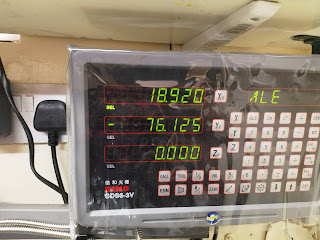
DRO on the Myford makes repeatability a doddle.
First two boxes done. I wasn't that happy with how well centred these were to be honest. I think I need to improve my DTI holder and possibly my method as well.... Its not super critical on a tender and I can match up pairs but I want to do a nice job of this.
5/16" hole gives end clearance to the axle which Curly says will be able to float in the bearing, not sure that is good practice as the axle could spin in the inner race. I'll ask at the club and see what people think.....


Comments
Post a Comment